A published snapshot of a workshop tool, 21 September 2026. The live version runs on the shop LAN, where the result sheets save to disk and the 3D viewer talks to the printer.
Breadboard Bench / build hub
check.py ALL CLEARscrews.py ALL SCREWS OKrev 2026-08-24
Where the build stands
Print-readiness review blockers6 / 6 fixed
Geometry gate (check.py)ALL CLEAR
Fastener gate (screws.py)ALL SCREWS OK
Interference sweep (side bin)0.000 mm³
Export freshness guardACTIVE
The structure is print-ready; board retention is not. Plates 01 and 02
and their follow-ups are printed and read back, and eleven constants are
settled. What is still moving is how a breadboard is held: the printed
indexing teeth failed three times and have been dropped for the board's
own dovetail cleats, which is what the Storyboard's last panels cover. Every blocker from the August print review is fixed and
re-gated. Since then the bench grew a universal display mount (an open
H-frame sized for the Elecrow 7″ CrowPanel, T-slots with captive
square nuts), a side bin that snaps on magnetically to the steel
bar-end screw heads (three N52 discs, nothing visible, nothing cut into
the frame), and the expressed rail-joint buttress chosen from the
workflow’s verified options.
Nothing gets trusted by eye: geometry, fasteners, freshness and
interference are all measured on every rebuild.
Next at the printer
Cut a span gauge to the measured 65.21 and print it — the last open constant
Redraw deck_rail() around pocket and peg; drop the indexing teeth
Decide the rail counterbore for the M3 × 12 cap screws
Make the CAD changes on the PC, re-gate, then slice plate 04
Plate 03 in PETG: the clip trio on edge, the production regime
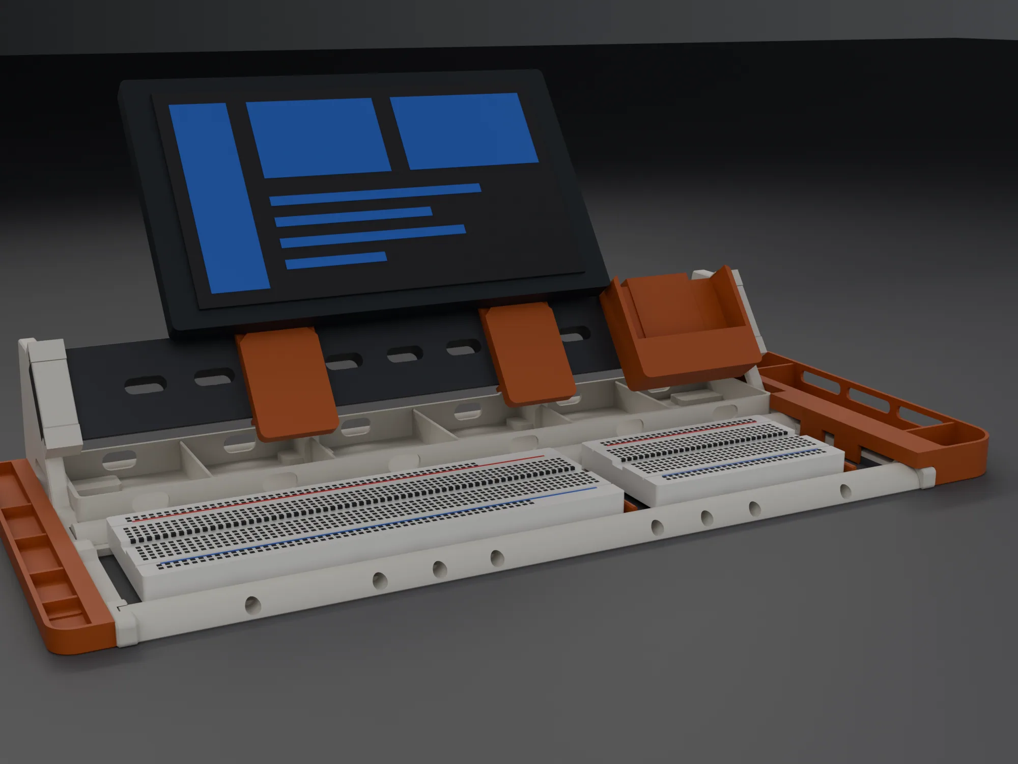
bench 300 × 165 mm · +35 side bin · display face 19 mm off rail
PLA structure 170.1 cm³ · frame total 281.7 cm³ · 22 TPU inserts · 14 screws · 17 magnets
drag to orbit · parts list toggles subassemblies · explode slider pulls the build apartframe: tie seated full-length, display on two clip-on posts — current
19 September 2026 · plate 02 and what it taught us
Storyboard
0.15
RAIL_FIT_MORTISE
rail slot clearance
0.20
SOCKET CLEARANCE
round bar seats — already correct
+0.30
FOOT POCKET
16.30 × 6.30 mm
6.25
MAGNET_FIT
pocket for a 6 mm disc
0.00
SHRINK
152.00 and 84.01 as drawn
9.32
VS 9.0 LIMIT
M3×16 cap bottoms out — see 21
MATTE
SCREWS HOLD
cleared for the whole structure
0.80
RAIL_PAD_D
O-ring pocket, 1 dot — replaces the TPU pad
1FIXED · see 2 and 3
The rail's lips sagged
Where it started: printed over thin air, no support.
The fat bar fits best in 2 dots. The thin bar only fits its own small hole, which is the design working. The frames are already cut at 0.2 — nothing to change.
No rock, paper slides down both sides. The board's dovetail pegs are a touch awkward but fine — grooving for them would pin the board to one spot and kill the 2 mm sliding.
It reaches 9.32 past the rail. The shallowest hole is 9.0, so it hits the bottom before it clamps. Counterbore + M3 × 12 reaches 7.8 and fits everywhere.
The printed teeth are finished — they failed on plate 02d, they failed again on a full-size print, and the reason is a process limit rather than a tuning one: a triangular tooth cannot print its own tip. So retention moves onto a feature the board already has. One rail carries an open pocket its dovetail tab falls into; the opposite rail carries a peg that falls into the notch across from it. The board goes straight down onto both.
The tab is 5.20 tall, 4.07 across its tip and stands 1.41 proud, and its bottom is flush with the board's underside. The pocket is cut 0.3 wider and open at the top, so the tab drops in rather than sliding along. Nothing here relies on the tab's 3° undercut: 0.11 mm per side is smaller than this printer's own pocket error.
The other edge is female, and its notch sits directly opposite a tab. A peg 3.8 wide drops in cleanly — four dots on the peg gauge — which also puts the notch’s mouth at 4.00 or wider. That mouth was the one dimension on this board still being guessed at, because a notch that mirrors the tab is narrowest where you enter it.
The first cradle gauges were severed by their own tape relief — it was cut the full depth of the floor, so the part that exists to hold a measured gap came out as two separate pieces. is_watertight passed all three, because two disjoint closed solids are each watertight. A body count is the check that catches it, and it has since caught a second, unrelated floating-geometry bug in another gauge.
Two dots across is the fit: rails 55.14 apart, 0.40 of clearance on the board’s 54.74 plain width. Along the board is less settled. The stations measure 65.21 tip centre to tip centre, and there are three cleats per edge, not two — an earlier estimate of “about 71” was wrong by two hole pitches and sent a whole plate of gauges out too wide. A slotted second pocket may remove the need for that number to be exact at all.
Two constants are settled and one is not: the station span needs a gauge cut to 65.21. Then the rail counterbore decision, the CAD changes, and plate 04.
Measured off the exported models, not typed in
Catalogue
Every printed piece of the bench with its exact size. Sizes are the part as modelled, length × width × height in millimetres; “as printed” is the same part turned the way it sits on the plate. Weights are solid-equivalent at the filament's density — sliced parts weigh 50–65% of that. The whole bench first:
Test pieces
The gauges: small parts printed to settle a fit before the big part that depends on it. None of them ends up in the bench.
Hardware and electronics
Everything that goes into the bench that is not printed. Where the assembly carries a model of the item, its size is measured off that model and its quantity is the number of copies in the assembly; items the assembly does not model are drawn to their standard's nominal size and marked so.
Design constants
Every numeric constant in cad/params.py and cad/frame.py, with the note written beside it in the source. These are the numbers the parts are generated from.
True orthographic views, 1 drawing unit = 1 mm
Schematics
The assembled bench from the front, from above and from the right. The views are rendered from the seated assembly at exactly 5 pixels per millimetre and the dimension lines are drawn over them in the same millimetres, so each number sits on the geometry it measures. Heights are taken from the desk: the bench stands on TPU pads 1.0 mm proud of the printed parts. Orange parts are PETG, red is TPU, the dark bar is the DIN rail, grey-blue is the display and breadboards.
Full-quality stills · 2000 × 1500, 320 samples
Frame — skeletal, open back
The newer design: the panel is deleted, the DIN rail is the structure, the
rear tray carries storage and stiffness. Everything below the modules is
open on purpose.
Console — moulded, solid back
The earlier philosophy: one big print with wells and bins moulded in, and a
solid raked rear panel the rail screws to — the white wall in the rear
view.
Display mount — v1 H-frame vs v2 posts
v2 is now what the frame ships. v1 was spine + two uprights + two
crossbars: 5 parts, 63.4 cm³, ~81 g, plus eight M3 × 12 that
existed only to bolt the mount to itself. v2 is one part printed twice
— a T-slot post with its own clip — spaced on the rail to the
display’s holes: 2 parts, 25.1 cm³, ~32 g. 60% less
plastic. The uprights only ever needed a spine because their spacing
was fixed; the rail already gives X and each post’s slot gives Y, so
nothing is left that exists just to hold other parts. v1 is still
selectable in the 3D viewer as Mount v1.
Breadboard retention — five concepts
Nothing stops a board sliding along the 288 mm cradle today. Each concept
below is staged on the real deck at the 830/400 boundary. Stops in orange.
Side-bin form studies
Rendered in the same studio as the stills
Motion
TurntableThe model rotates under fixed studio light, so the key and rim rake across every surface. Loops.Assembly sequence (first cut)The August exploded-view fly-in. Superseded: the software test fit showed this order cannot be built — the bars cannot drop into standing frames, and the rail does not descend onto the posts. Kept for the look; follow the verified build instead.Verified buildThe order the meshes allow, every move checked for collisions by cad/assembly_fit_check.py: ladder and tie down, tray onto the tie, frames close in along x, end screws, gaskets into their glands, the DIN rail slides through both mortises, rail screws along the post slope, caps, stops, side tray and bin, then the clip-on modules and the boards. Feet and magnets ride in with the part that holds them. The clip-on modules rock onto the rail by hand and are the one step not checked.Stage 2 fit testHow the plate-02 test board is used: rail stub into three slots, bars into the sockets, pads into the foot gauge. Captioned step by step on the Build plan tab.
What gets printed, and how
Build sheet
Print settings — per part
Part
Mat.
Layer
Walls
Infill
Brim
Supports
End frame (L + R, two STLs)
PLA
0.2
3
15%
no
no
Deck ladder
PLA
0.2
3
15%
yes
no
Rear tie
PLA
0.2
4
25%
yes
no
DIN rail (structural)
PLA
0.2
4–6
25%
no
no
Rear tray
PLA
0.28
4
15%
no
no
Board plates, carrier
PETG
0.2
3
15%
yes
2 dabs, clip channel
Screen bezel, rail bin
PETG
0.2
3
15%
no
2 dabs, clip channel
Display post ×2 (mount v2 — one part, printed twice)
PETG
0.2
3
25%
yes
2 dabs in clip channel
Side bin
PETG
0.2 only
3
15%
no
paint support under the rolled edge (8 mm cantilever); pause at Z = 3.2 for 2 magnets
Screw tray (left)
PETG
0.2 only
3
15%
no
pause at Z = 3.2 for 5 magnets
Rail cap ×2 (top face down)
PLA
0.2
3
100%
no
no
Deck stop ×2 (on its side)
PETG
0.2
3
100%
no
no
Rail pads ×4, foot pads ×18
TPU 95A
0.2
—
100%
no
no
0.4 nozzle. 0.2 mm everywhere except the rear tray,
which goes to 0.28 — it has ~190 layers of two isolated 6 × 25 mm
fins, and a coarser layer carries 40% more material each while cutting
the starved layer count by 30%.
The side bin and screw tray must stay at 0.2: their magnet pause
is at Z = 3.2, which is exactly 16 layers at 0.2 but has no layer
boundary at 0.28 — you would pause either before the pockets open
or after the roof has started. Coupon first — every fit constant is
read off a printed gauge before the big parts run.
Cooling — Filament settings → Cooling
Setting
Value
Where / why
Chamber temperature
0
Every plate. The H2S actively holds up to 65 °C. N52 fades permanently above ~80 °C, and nearly every part here is cooling-starved. Check it is not still hot from an ABS job
Slow printing down for better layer cooling
on
Stock default is already on
Max fan speed threshold (layer time)
8 s
End-frame plate and rear-tray plate only. Stock is 4 s. Do NOT raise it globally — at the H2S's 21 mm³/s almost the whole build sits under 8 s, so a blanket setting forces min speed everywhere and roughly doubles print time
Part cooling fan
100%
Those two plates
Support → On build plate only
on
Side bin and screw tray. Their magnet pockets are sealed voids; “everywhere” (especially tree) can colonise an internal cavity, and you would not see it until the magnets refuse to seat. Slice, drag to layer 16, confirm seven open holes
Measured at 21 mm³/s (verified H2S max volumetric flow
for PLA, standard hardened steel nozzle; 40 with the High Flow hotend).
Layers under 8 s, per part: end frame 298 of 300 — the worst in
the build, and it carries the rail mortise; rear tray 195; side bin,
screw tray, ladder, rail and tie all zero.
Hardware
Item
Qty
Where
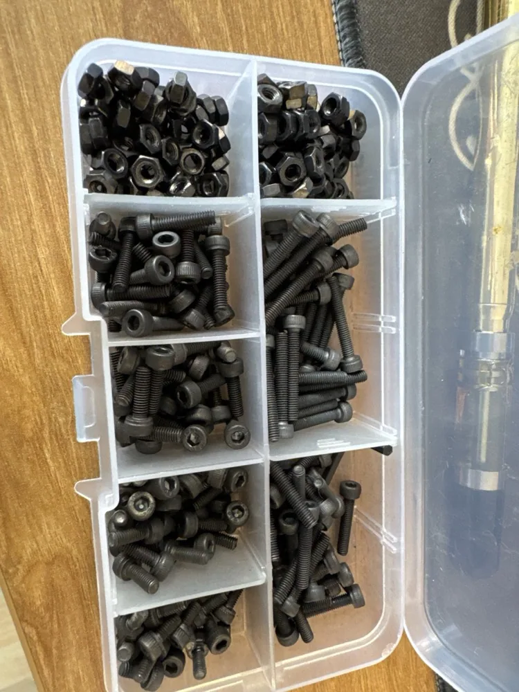
M3 × 12 socket head cap, black-oxide alloy steel (ISO 4762)
6
Bar ends, through the frames — the magnetic six; alloy steel grips hardest, stainless will not hold
N52 neodymium disc Ø6 × 2
17
3 + 3 in the bin and tray back walls (in sideways through the head pockets; captive between skin and screw head once mounted). 2 in the bin’s screw cells + 5 in the tray’s: pause-and-insert — pause at Z = 3.2 mm, drop in, resume, and the print seals them under. 2 in each rail cap, press fit (the cap is 2.45 thick, nothing to seal under). Never heat a magnet — N52 fades permanently above ~80 °C, so chamber = 0
M3 × 16 countersunk, carbon steel
4
DIN rail at the end frames, flush in the clip face — hide under magnetic rail caps, so not stainless
M3 × 14 countersunk
4
DIN rail at the tray buttresses — the buttress pilots are 9.0 deep; a ×16 bottoms out before its head seats (DFM review)
M3 × 8 pan head
2–4
Display flange screws into the posts' slots, captive square nuts (12 mm if the flange is thick). Mount v2 needs no spine or crossbar screws — the eight M3 × 12 pan heads v1 used are gone
M3 hex nut (DIN 934, 5.5 AF × 2.4) — the ones on hand
~8
Nut channel on the back of each display post, loaded from the top. The channel was drawn for a DIN 562 square nut (5.5 × 1.8); a hex nut fits, cannot turn in the 5.8 mm channel, and stands 0.2 mm proud of the back face into free air. Snug, do not crank: it bears on less ledge than a square nut
Regenerating
python cad/bench.py        # console + shared modules
python cad/frame.py        # frame variant + side bin
python cad/coupon.py       # console fit gauges
python cad/coupon_frame.py # frame fit gauges
python cad/check.py        # printability + freshness
python cad/screws.py       # every fastener, measured
python cad/build_viewer.py # the 3D viewer tab
check.py fails stale exports: an STL older than the code
that generates it can’t pass. That guard has caught real drift twice.
Result sheets · tapped at the printer · what they settled
Checks
Every printed gauge exists to settle a number, and a number that stays in your head is a number
the CAD never gets. On the workshop LAN these are tap-through sheets on an iPad that save to disk
as you go and work the constant out for you. Here they are the results: what was answered, and
the constants that went back into the CAD.
Plate 01 - TPU
PLATE 01
Caliper readings for the TPU pads and the control block, spoken rather than typed so both hands stay on the caliper. Settles FOOT_FIT and how much TPU over-prints on this machine.
15 answered
Plate 02 - fits
PLATES 02, 02B, 02C, 02D
Push each printed gauge into its slot and tap what happened. Settles the rail slot, the round sockets, the foot pocket, the pilot screws, the gasket and the magnet caps.
25 answered · complete
RAIL_FIT_MORTISE0.15
FOOT_POCKET_OVER0.3
ORING_GASKETworks
RAIL_PAD_D0.8
MATTE_PILOT_STRENGTHpass
MAGNET_FIT6.25
span_loss_2880.0
LADDER_SHELFpass
Cleat gauges
PLATES 02E-02I
The board retention rework: drop a breadboard onto each gauge by its own dovetail cleats. Settles the rail gap and the station span that replace the indexing teeth.
2 of 16 answered
PEG_W3.8
NOTCH_MOUTH_MIN4
RAIL_GAP55.14
BOARD_CLEAR0.4
Staged pilot build · cheapest plate first · nothing prints until its fits have passed
Build plan
Never print a part until every fit it depends on has passed on something
smaller. Click a stage for its files and checks. Ticks persist here.
Every stage below is already a Bambu Studio project.out/plates/ holds one .3mf per stage — right machine,
right filament, parts in their gated print pose, per-object wall / infill / brim
overrides applied. Open 01_tpu_regime.3mf and print. The per-plate
card, including the two things a .3mf cannot carry (painted support
dabs, and the Z = 3.2 magnet pause on stage 9), is
out/plates/PLATES.md. Regenerate with python cad/plates.py.
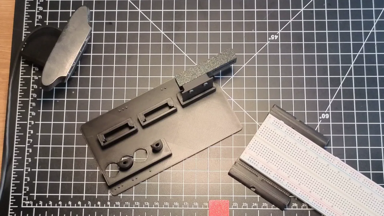
Stage 2 · how the fit test worksThe big flat piece on plate 02 is a test board, not a bench part: the same joint cut at three clearances, marked with 1, 2 or 3 dots. The loose pieces from the same plate get pushed into it by hand, and the winner’s number goes into the design. The loose pieces are drawn in orange so they read against the board — yours are all the same PLA. Which slot wins in the film is made up; yours is whatever your print says.
Rail-joint rework · 5 designs × 3 angles · every option double-verified by adversarial agents
Joint study
The question under review: the end frame’s rail joint reads as a thick
block patched behind the mortise, and its gasket pocket (the indent) may be
redundant now the shroud captures the rail by shape. Each candidate below
was built as real geometry by an independent agent, then attacked
by two more (structural + printability). Angles: front three-quarter,
rear-top (boss depth and gasket land), inner-face silhouette.
Click any image to zoom.
Tie-rod joint · second pass · no brackets
Where the tray meets the rear tie
The first pass asked “what bracket holds the rod?” and got
five trapezoids for an answer. Wrong question. The actual offence is
that TRAY_Y1 sits at
TIE_Y − TIE_R − 2, so there is a
2 mm slot running the whole 288 mm between the tray's rear wall
and the rod. That slot is the gap — and the tails were lumps stuck
on to bridge it.
So: delete both tails and let the rear wall do the job along its entire
length. The wall comes down and lands on the rod, and the rod's
own cutter carves the mating surface, so the fit is conforming by
construction and there is nothing to align. Contact goes from
21 mm² to ~1400 mm² — and the part count goes
down, not up.
How far back the wall may come is not a style choice. The tray
prints upright, so the wall's underside may not exceed 45°. That
lands it exactly on the rod's 45° tangent point, y = 144.65
— the geometry hands over the design line for free. The three
options differ only in how the wall face gets there.
Buttress tops · a printability study, measured
Two seconds a layer, 190 layers running
The tray is 288 × 53 × 53 and 61 g. Below z = 14 it
prints 1 300–14 000 mm² layers. Above the rim it collapses to
two isolated 6 × 25 mm fins and stays there for ~190 layers
— 4.8 s at the rim, 2.3 s at the rail land. Nothing
cools before the next layer lands, and it happens on the one surface that
has to be accurate.
Geometry can only do so much. Layer time = area × height
÷ flow, so 8 s at 0.2 mm and 12 mm³/s needs
~480 mm² — more than 3× what the fins give, and the
H2S runs faster than 12, which makes every number here optimistic. All
times below are measured off the real solids at 0.2 mm / 12 mm³/s.
First pass — five brackets, rejected
Kept for the record and for one genuinely useful finding: the tie's
flat sits on the desk plane, so nothing can reach under it.
No closed eye, no hook below centreline, no split bearing — the
build proved that last one by handing back a U-block whose two cheeks
were separate solids with nothing to join them. Every bracket could
only ever work the top 180°, and every one of them read as a
trapezoid bolted to the back.